M2 is a CFR Part 21 Parts Manufacturer, designing unique products for Piper Aircraft.
Installation Overview
Preparation for installation
Prepping for Doubler Installation
Layout of the new Access Hole

Please read the entire Installation Instruction Manual (provided with the Kit) before starting the modification. Locate and remove the Main Landing Gear Strut Servicing Access "Plug or Wilkie" Button on the upper wing surface.
Layout of the new Access Hole
Prepping for Doubler Installation
Layout of the new Access Hole

The Red Air Valve Cap provided with the Kit has a indentation in the center to aid in locating the exact center of the strut. Insert the compass leg into the indentation and trace the dimension of the new Access Hole onto the upper wing surface. The Installation Instructions provided with the Kit will explain this step further.
Prepping for Doubler Installation
Prepping for Doubler Installation
Prepping for Doubler Installation

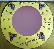
The Doublers are shipped to you treated, primed and pre-drilled for ease of installation.
Use EXTREME care when working with the upper wing surface. (The skin is .025 and is very unforgiving of any unnecessary pressure. This may stretch the skin and could cause problems with the final installation). The rivet holes in the wing skin will be countersunk for NAS1097AD3 rivets.
Doublers ready for installation
Doublers ready for installation
Prepping for Doubler Installation

The First Layer Internal Doubler and Second Layer Internal doubler and Nut Plates have been positioned for installation. Prior to installation coat the upper surfaces of both Doublers with a thin layer of pro-seal.
Doublers installed
Doublers ready for installation
Doublers installed

The First Layer Internal Doubler and Second Layer Internal doubler and Nut Plates have been installed.
Gear Installed
Doublers ready for installation
Doublers installed

Doublers are in place and Main Landing Gear is installed.
Installation Complete!!

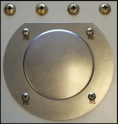
The Cover Plate is designed to cover all of the rivet heads that were used in the installation so there is no need for any paint cover up or matching.